Contact Us
Cable Tray Automatic Production Line

Cable Tray Automatic Production Line

hcm 600 cable tray automatic production line

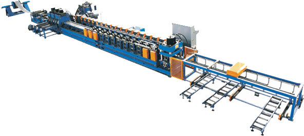
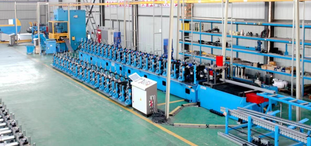
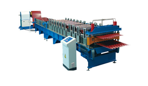
HCM-600 Cable Tray Automatic Production Line adopts metal sheet coils as raw material, can make the sheet into specific shapes and specifications through decoiling, leveling, punching, notching, roll forming. The whole cable tray production machine adopts PLC control, AC frequency conversion speed regulation technology, to realize automatic continuous production, it is ideal equipment for steel structure and metal cold forming industry.

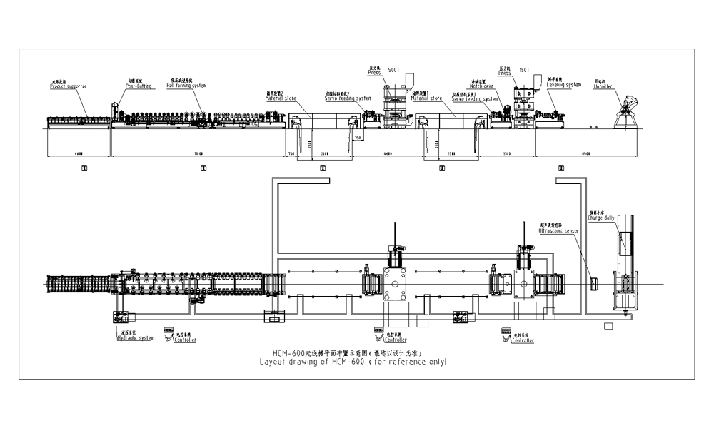
Work flow of the cable tray production line: Decoiling →Leveling→Punching & notching →Storage→Roll forming→Straightening→Cutting→Output

Jinggong is one of the top cable tray roll forming manufactures in China. Feel free to contact us if you are interested in the cable tray machine price.

Video of HCM-600 Cable Tray Automatic Production Line

Technical parameter of HCM-600 Cable Tray Automatic Production Line:

No.

Item

Parameter

Remark

1


Suitable material

Type

GI sheet


Thickness(mm)

0.8-1.5mm


Yield strength (Mpa)

235


Width(mm)

According to the actual


2

Producing speed(m/min)

2-4


3

Forming motor power (KW)

15

According to the actual design

4

Decoiler motor power (KW)

2.2

According to the actual design

5

Decoiler hydraulic station motor power (KW)

5.5

According to the actual design

6

Leveling motor power (KW)

2.2

According to the actual design

7

Servo loading motor power (KW)

3.3X2

According to the actual design

8

Press machine power (KW)

70

According to the actual design

9

Transfer car motor power (KW)

2.2X2

According to the actual design

10

Main hydraulic station power (KW)

4

According to the actual design

11

Forming transverse motor power (KW)

1.1X4

According to the actual design

12

Output motor power (KW)

0.75

According to the actual design

13

Total power

About 115

According to the actual design

14

Power supply

AC380V,50Hz,3 phase


Working Process Layout Of HCM-600 Cable Tray Automatic Production Line

Download
Cantilever type automatic decoiler

1. Functional configuration

Structure

Decoiling mode

Expanding mode

Press arm

Coil car

Hydraulic system

Electrical system

Cantilever

Motor

Hydraulic

Yes

Yes

Separate

Separate

2. Technical parameter

Max.Capacity                5T

Suitable coil ID              φ508,610mm

Suitable coil width(Max.)      1000mm

3. Main structure

a)The structure is cantilever type.

b)The cable tray making machine frame adopts sectional material, steel plate for welding and processed by blast.

c)The hydraulic device expands the inner support plates to realize the radial tension.

d)Motor and chain drive the decoiler shaft to rotate, the sensor output signal will change according to the output coil sheet, the inverter will adjust the rotation speed to realize automatic decoiling.

e)Press cylinder drives the arm to go up and down. (customer prepare the air supply)

f)Adopt separate hydraulic station, provide the power for steel coil expanding and coil car lifting.

g)Before working, lift the coil on the coil car by manual lifting equipment, then realize the coil’s lifting, sideway and loading on the decoiler shaft, expand the inner hole, adjust the brake, and feed the sheet to forming roller until the roll drags the sheet. After that, the hydraulic decoiler will release the coil automatically under the control of ultrasonic sensor to meet the requirement of the roll forming machine.


Leveling system

Leveling system consists of several front and rear convey rollers and 7 level rollers. The through the convey roller the sheet pass through the level roller to eliminate the uneven on the surface and reduce or weaken the stress inside the sheet, make the sheet more favorable for the later working procedure. According to different sheet thickness, can adjust the gap between the level roller by manual, make the level device achieve the best leveling effect.

Main parameter:

Feeding roller: 9Cr2Mo or GCr15, hardness after quenching HRC55-60

Press machine and punching

According to different profiles and punching position, set front and rear press machine, to punch the different position holes on the profile. The front press machine is used for punching both sides of the height direction, the rear press machine is used for punching the holes on the bottom.

Prepare 4 groups of front punch moulds to make the corresponding specifications, change the moulds according the moulds No. To confirm the moulds left and right position through locating pins. On the bottom plate10 has some locating holes, when produce the maximum specification, the locating pins will be positioned at the outermost position holes. In the picture below, upper mould carrier2, guider sleeve3, backing board4, setting plate5, punch head6, punch die7, lower mould carrier9 complete a whole body, can move left and right along the guide rail 8 under the influence of manpower.Rear punch device is same as front punch, consists of hydraulic machine and punch moulds, according to the width specification requirement, this punch device equips with 8 sets of moulds. It needs to change the punch moulds by manual to realize all the bottom punching.


Main parameter:

Front press machine capacity: About 150T (Based on the actual calculation)

Rear press machine capacity: About 500T (Based on the actual calculation)

Punch head material: Cr12MoV, hardness after quenching HRC58-62.


Notching device

The notching device can perform automatic notching and manual notching. Automatic notching uses for volume production after length fixed, manual notching uses for casual inspection.

When the product reach to corresponding length, main machine stops, the cutter blades goes down, to make the notching one both sides of flat sheet and the middle locating holes. When the limit block touch the lower limit switch, the hydraulic cylinder drives the active plate to carry on the lift immediately, until touch the upper limit switch, this process completes, the main machine start again. Besides, when the profile specification changes, need to control the notching mould carrier to left or right by rotating the adjust hand wheel.

Main parameter:

Punch head material: Cr12MoV, hardness after quenching HRC58-62.

Servo loading system

This servo loading system consists of convey roller and guiding device. The guiding device consists of guide roller and adjusting structure. The main function of loading parts is to pull out the sheet from the press machine and convey to the forming machine. This structure adopts high precision servo motor to provide power to ensure the accuracy of metal sheet feeding. Through the chain, drive the front and back two convey roller and then drive the metal sheet forward, there are guardrails around.

Main parameter:

Each step: 200mm

Storage device

This production line has 2 sets of storage devices, between the front press machine and rear machine, between the rear machine and roll forming machine. The storage device consists of bracket, hydraulic cylinder etc. The storage device installed in the material pit, the bracket can move up and down through the action of hydraulic cylinder. During the normal production, the bracket drops to the pit.

Main parameter: (according to the actual design)

Material pit length: 3500 mm

Material pit depth: 2000 mm

Roll forming system

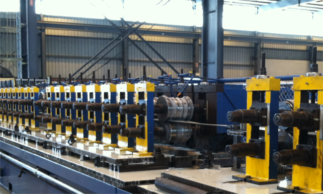
The roll forming machine consists of drive motor, machine frame, forming rollers, workpiece specification adjust device

1) The machine frame adopts 32# steel as primary beam, reinforced plate welded in the middle

2) Roller material adopts Cr12,hardness after quenching HRC58-62. Surface polishing treatment

3) Forming roller adopts two sides separate forming, disconnect in the middle, adopts intermediate datum and adjust from two sides to the middle. According to the workpiece specifications, adjust the screw rod pair by motor, between  two sliding screw rods use bevel gear drive to achieve full synchronization and it has self-lock function. The thickness adjustment to be realized by adjust the eccentricity of passive roller

4) Forming machine equips with integral cover to improve operation safety

5) Forming machine maximum adjusting width: effective 600mm

Cutting system

The cutting system consists of automatic cutting and manual cutting two parts. Automatic cutting uses for volume production after length calculation, manual cutting uses for casual inspection. When the product reach to corresponding length, main machine stop, cutter blades goes down to cut the panel, limit block touches the lower limit switch, then lift up immediately and touches the upper limit switch, the process complete, and main machine start to run again.

It needs to change different cutter blades when producing different profiles. There are 8 sets of cutter blades.

Main parameter:

Cutter blades material: Cr12MoV, hardness after quenching HRC58-62.

Support table

The support table put after the cutter of main machine, it mainly consists of a single side adjustable guide roll group and roll wheel mounted at an inclined angle, each of four rollers is assembled on the rolling shaft. Each rolling shaft is active, powered by the reducer. To adjust the left and right position of guide roller group to realize the production of multiple specifications.

When adjusting the guide roll group, the guide roll group should be in a straight line and adjusted according to the width of panel.

Main parameter: 

Support table length: 4m

Electrical control system

1)Adopts PLC control technology, frequency conversion speed regulation technology, realize the automatic production of the whole machine.

2)The system provides friendly man-machine interface, can set batch, workpiece length, quantity, etc.

3)Operation mode: Touch screen+button

4)Encoder with counting and length counting function.

5)Adopt Mitsubishi PLC and inverter.

Hydraulic system

1)Hydraulic system provides the power for decoiler, punching and cutting system.

2)It consists of motor oil pump, hydraulic valves, press meter, filter etc.

3)Main hydraulic valves adopt Rexroth brand.

4)Hydraulic oil adopt No.46 antiwear hydraulic oil

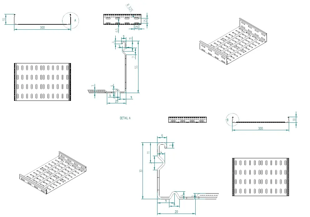
Profiles' parameters of Cable Tray Automatic Production Line

Cable Tray Automatic Production Line

Profiles of Cable Tray Automatic Production Line

Cable Tray Automatic Production Line
Start Now
Email us with inquiries or use our contact data. We would be happy to answer your questions.
Any Questions About Jinggong Building Materials Machinery?
Email us with inquiries or use our contact data.
GET IN TOUCH